Wiring Diagram – Stratocaster Mid Circuit Booster Kit Installation
Support / Fender Stratocaster Mid Circuit Booster Kit Installation
The Eric Clapton style Fender Stratocaster Mid Circuit Booster will require a bit of forward planning if you are installing this on a standard Stratocaster, as there will be some routing required for the PC Board and a Battery Box, which is not supplied.
What’s in the Kit?

Fender original parts include the following:
- PC Board
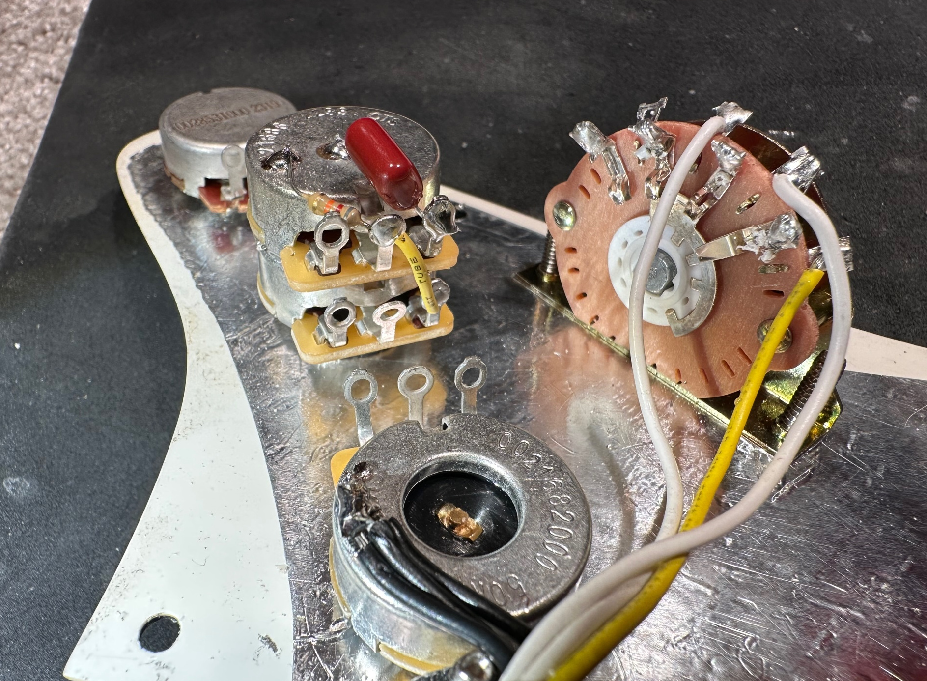
- TBX Tone Potentiometer
- Volume & Tone Potentiometers
- Tone Control Knob
- Stereo Output Jack
- Capacitor & 1/4 Watt Resistor
- Wiring Diagram
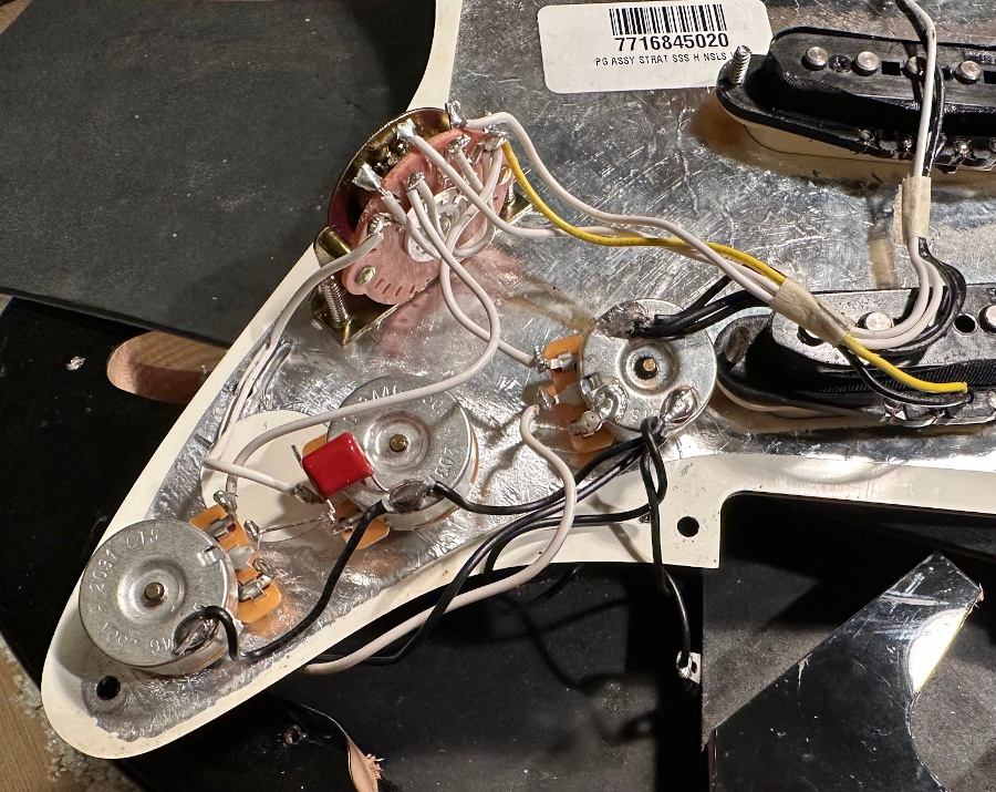
Wiring
There is a few things I should mention that may cause confusion. You will also need some additional wire
The 5 Way Switch
The pickups on the Fender wiring diagram connect to the other side on the switch in reserve. So just to explain this, if you are doing a complete install with a new switch then go with the Fender guide, however if you are installing onto an existing switch with pickups already attached, there is no need to move the pickup wires.

On the Fender wiring diagram its difficult to see the TBX tone Control connections.

Fitting Instructions
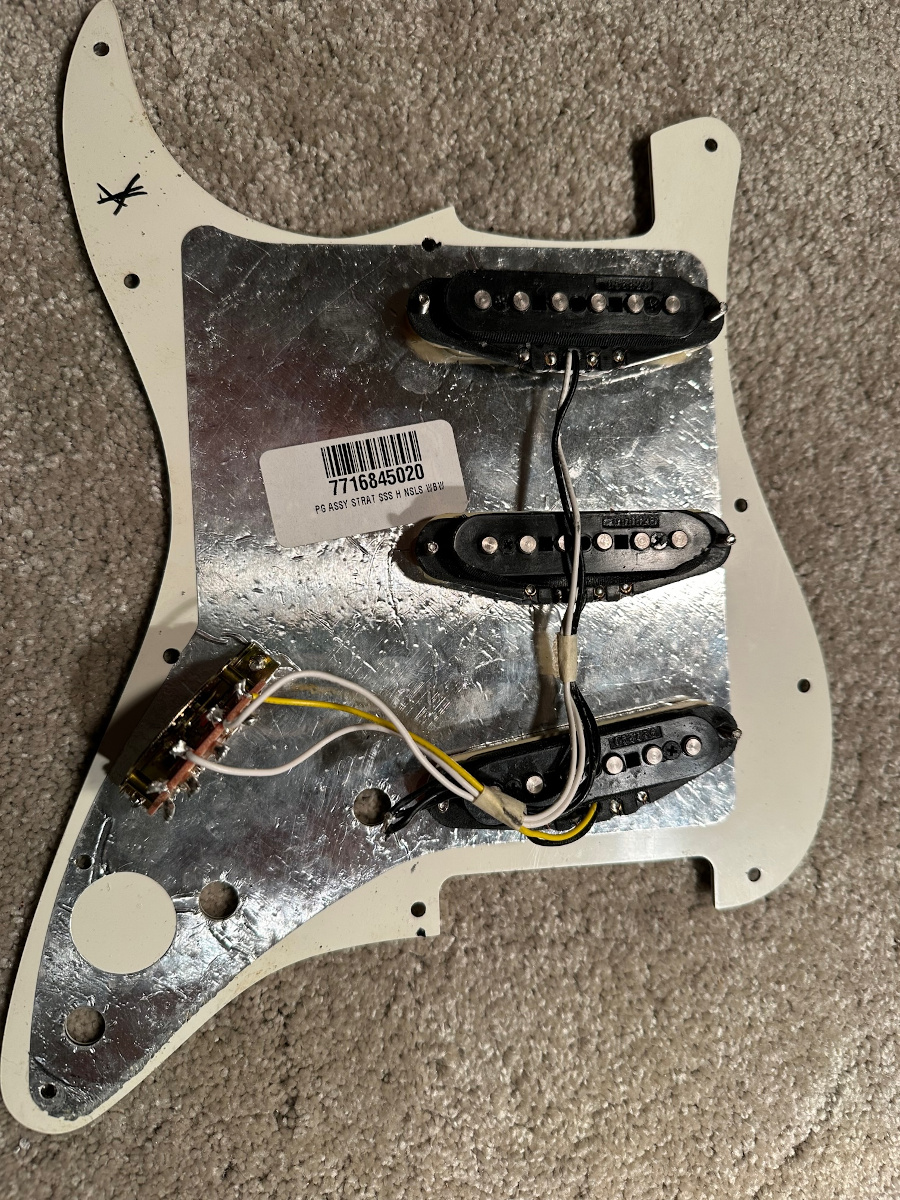
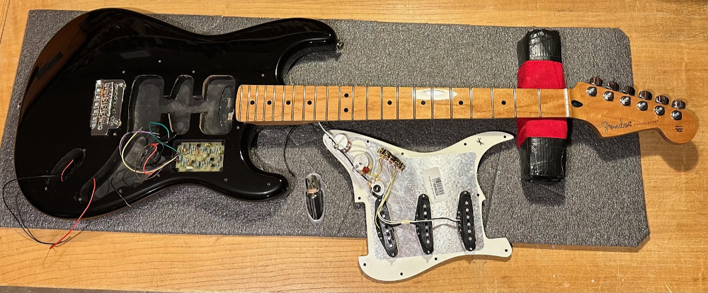
The good news is a Stratocaster is one of the more simple guitars to replace the wiring harness, because the wiring harness is attached to the large pickguard, which can be removed and worked on with ease. Of course there is some wood work involved too with the Mid Circuit Booster installation.
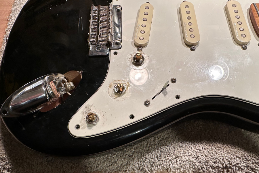
Removal
- Find somewhere safe, dry and secure to place your Stratocaster guitar while you work on it.
- Remove Strings.
- Undo the screws that hold the pickguard to the body. Do not undo the 6 x pickup screws by mistake.
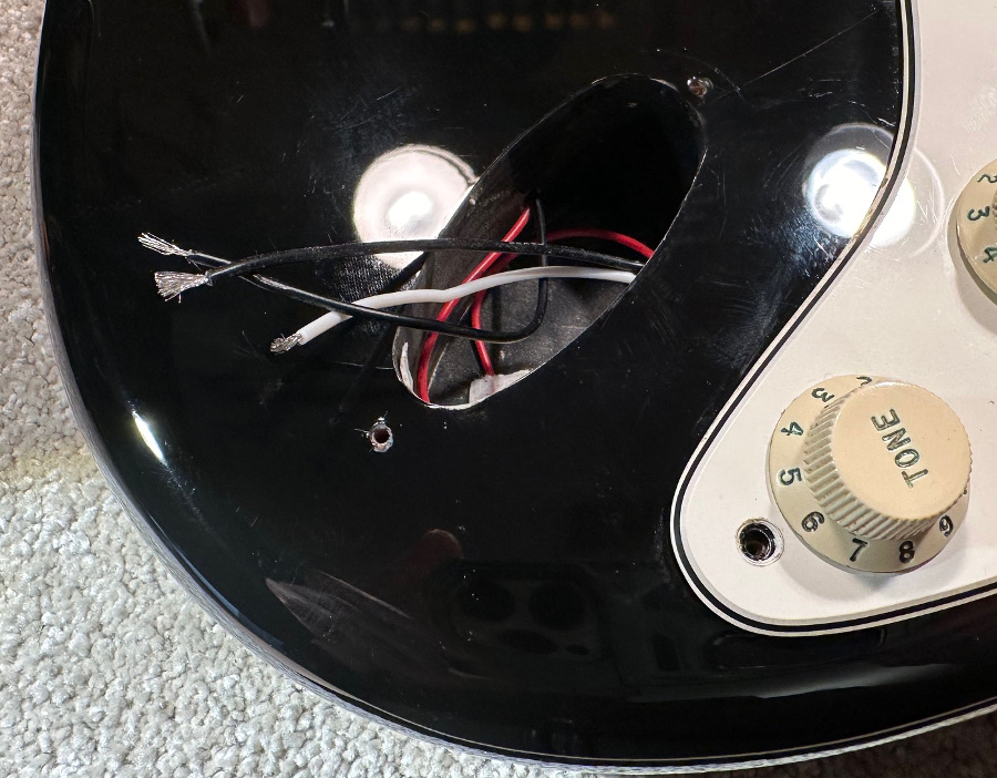
- Undo the 2 x screws that hold the jack socket housing.
- Carefully lift the pickguard up and cut all wires from the body to the pickguard closest to the pots. These are a few ground wires (normally black in colour) and the 2 x wires coming from the jack socket hole.
- Remove the jack socket housing and the pickguard away from the guitar.
- Put the guitar safely out the way for the time being.
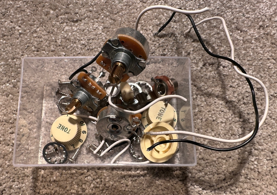
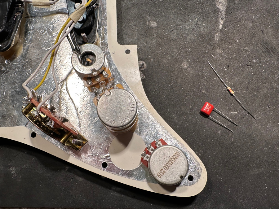
New Components
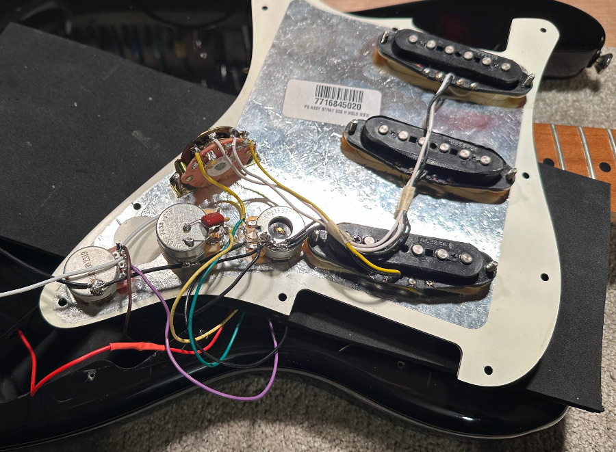
- Working on the pickguard, cut the 3 x pickup ground wires from the back of the pots, Normally soldered to the volume pot.
- Now cut the switch wires from the pots.
- You should now be able to remove all 3 old pots from the pickguard.
- At this point you may want to clean the front of pickguard where the old pots have been.
- You will need to check the size of the holes for the pots as on some pickguards they are drilled small for cheap electrical components. If they are small, the best way to enlarge them to 10mm to fit CTS pots, is to use a round file.
- The pickguard is now ready to fit the new harness parts.
- Please follow the wiring diagram below.
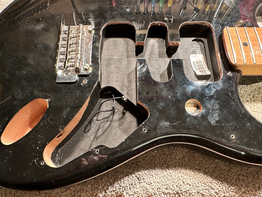
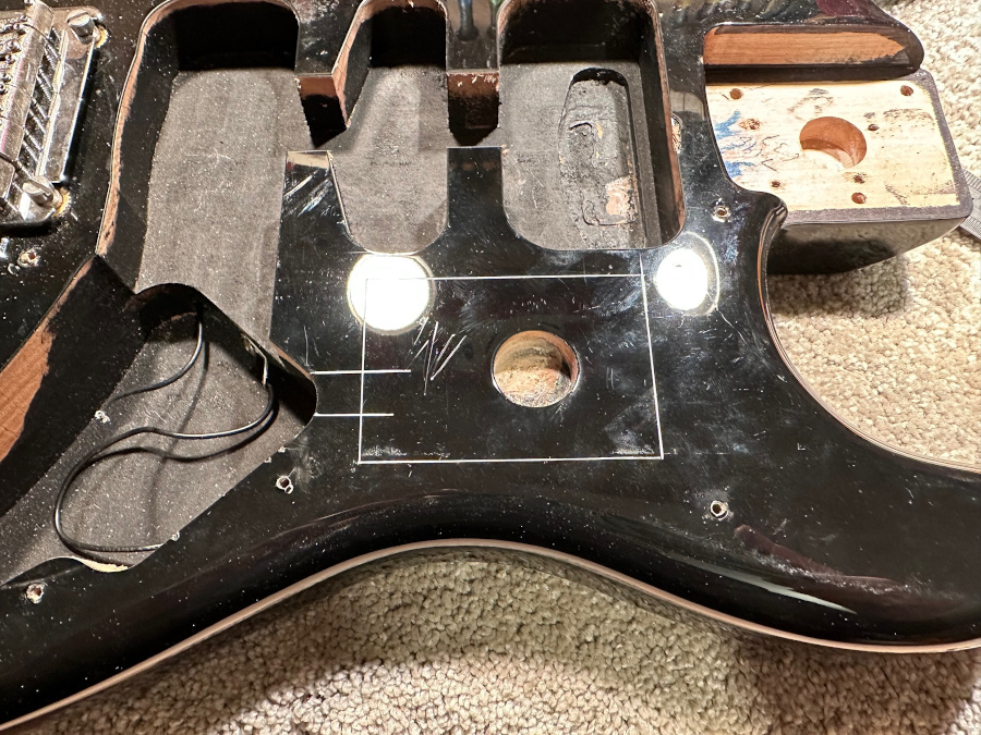
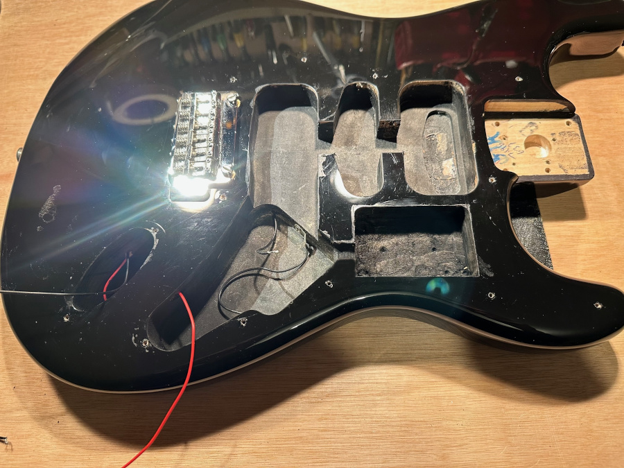
Woodwork / Routing
You will need to create two areas for the PC Board and the Battery to go.
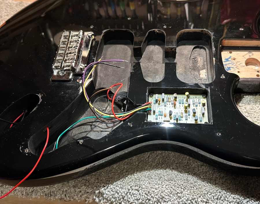
The PC Board
The PC Board can fit under the pickguard where you will need to route a hole 72mm x 47mm x 20mm. Mount the board on small rubber washers so the board is not sitting directly on the wood.
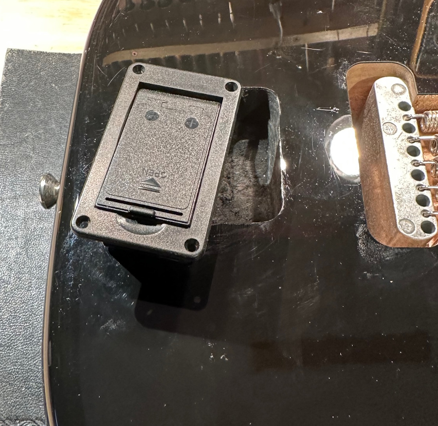
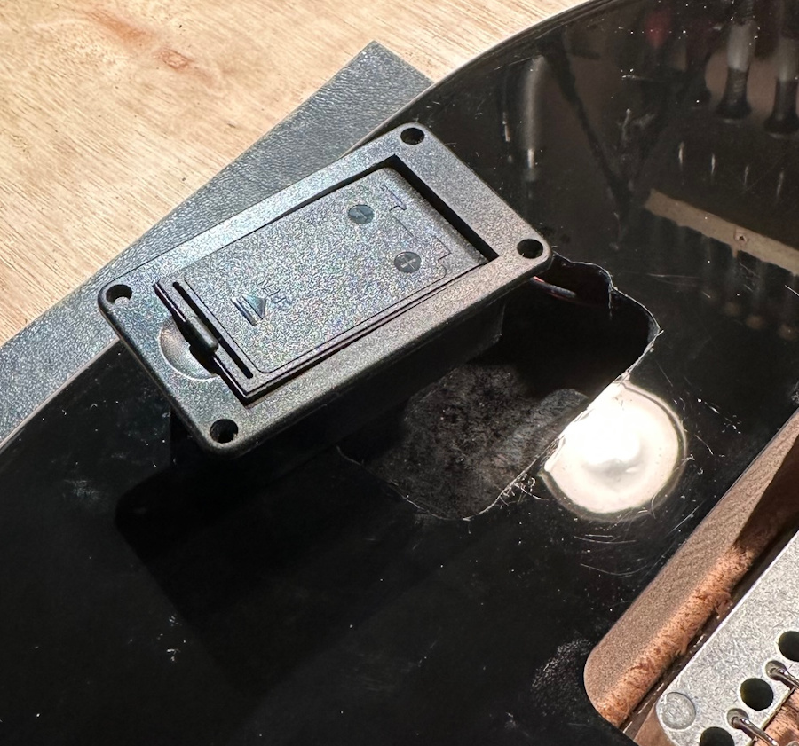
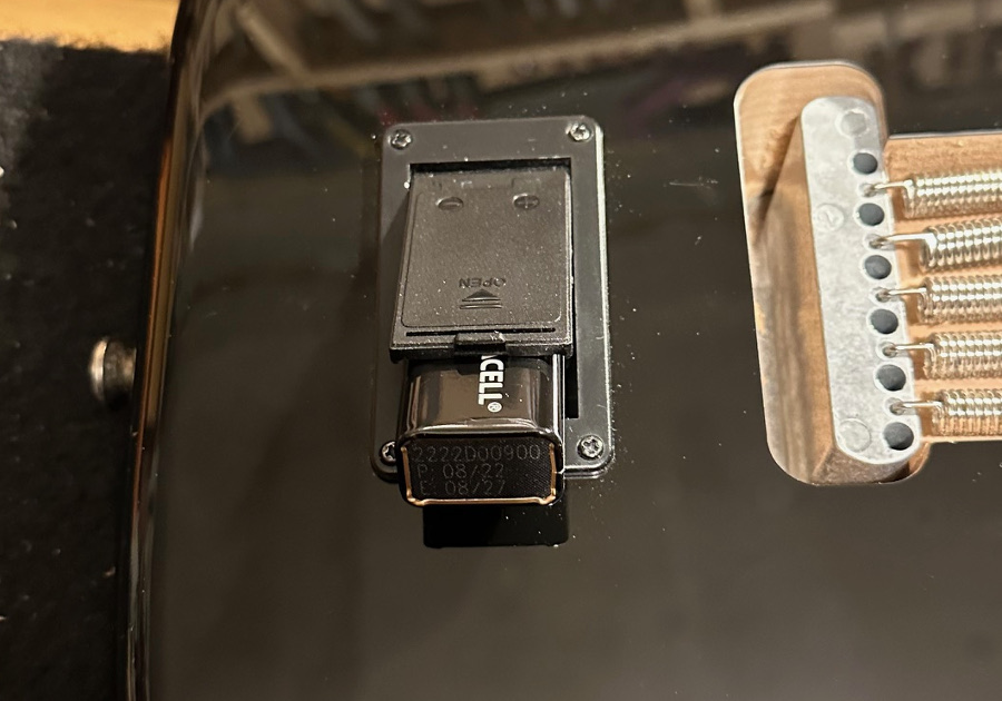
Battery Box
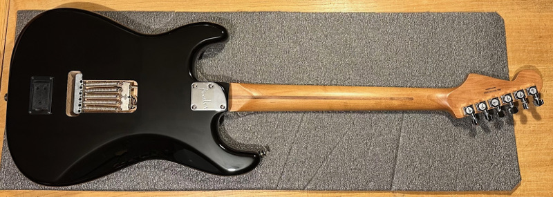
We fitted the battery on the back of the Stratocaster below the bridge opening and used a battery box that mounted the battery flat as apposed to the battery being mounted on its side. This meant I would not have to route so deep into the body, as some Strat
If you like and use our FREE Fender Stratocaster wiring diagram and would like to show your appreciation, please buy our team a coffee, thank you.
Support / Fender Stratocaster Mid Circuit Booster Kit Installation
Stratocaster bodies are thinner than others depending on make, model and year. You will also need to put a hole from the battery box to the jack socket compartment for the battery wires to run.

Stereo Jack Socket
The Jack socket area may need widening because of the size of the Stereo Jack Socket. We widened ours in the lower part of the Jack socket compartment so the top edge was not altered.
Reassembly
Once everything in in place you can do the following
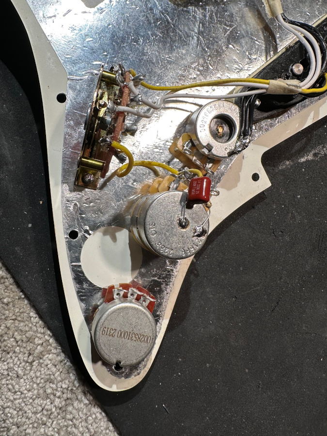
- Solder the 3 x ground pickup wires to the back of the new volume pot (refer to wiring diagram).
- The pickguard is now ready to go back into the guitar.
- With the pickguard resting next to the guitar, put the jack wires x 2 through to the jack socket area via the internal hole.
- Solder the ground leads to the volume pot.
- Fit the pickguard back into place, but don’t screw it down yet.
- Now replace the jack socket on the jack housing with the new one and solder the 2 x jack wires to it (refer to wiring diagram). You may need to shorten the wires.
- Screw the jack housing back into place.
Testing
- Plug the guitar into an amp and with something small and metal you should get a response from the pickups by gently tapping the pickup poles/posts. – Or you may have a Multimeter!
- If Everything is working, screw the pickguard into place and re-string.
Tools & Equipment
- Philips (Cross head) Screwdriver.
- Flat headed screwdriver on some models
- Small adjustable spanner/wrench.
- Good quality soldering iron.
- Wire Cutters.
- Router
- Masking tape for keeping things in place or out the way while working.
Tips
- When soldering the wires to the back of a pot, do not overheat / cook the pot.
- Keep wires tidy and neat and make sure all components are grounded.
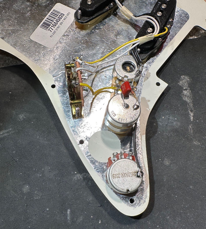
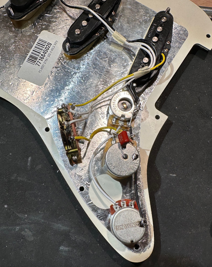
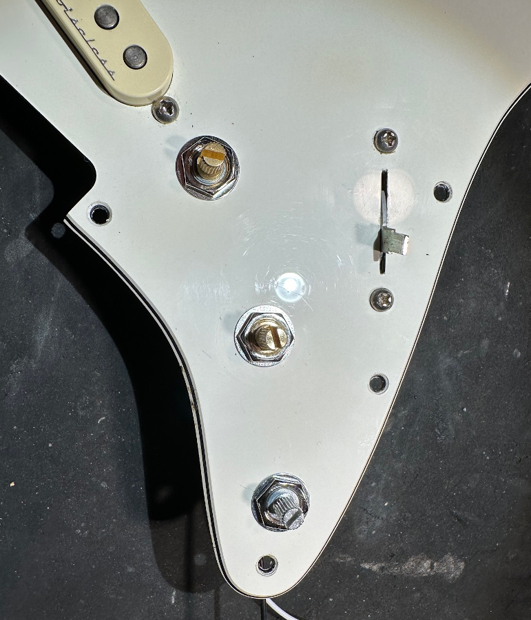
Stratocaster Mid Circuit Booster Kit Installation Photos

Need More Help? / Get in Touch
If you like and use our FREE Fender Stratocaster wiring diagram and would like to show your appreciation, please buy our team a coffee, thank you.